
Once you have selected a separate-panel fixture and fixed the lamp location, mark the proposed panel face and cable route on a site photo or elevation. Give the installer a dated shade log, a route measurement between identified endpoints and a record of which sample checks passed. A panel position can fit the wall even when cable reach or runtime is still unresolved.
If you are still deciding which fixture type to buy, start with the integrated vs separate-panel selection guide. This guide starts with a selected configuration and checks its proposed installation against the site and model documentation.
Match the site record to the quoted SKU
Use LMV-WL05-S-24W as a configuration example. The catalog lists a 24 W lamp rating, a 5 V, 35 W separate panel and a 3.2 V, 30 Ah battery. Copy the exact SKU and these listed values into the site record, then match them against the quotation and the sample documentation. The catalog values identify the configuration to review. The approved bracket, panel footprint, cable span and runtime each need their own evidence.
| Site check for LMV-WL05-S-24W | How to use the listed specification | Evidence needed before approval |
|---|---|---|
| Panel face and position | Use the 5 V, 35 W panel entry to identify the assembly to confirm. | Match the panel part, dimensions and approved bracket to the sample or drawing. Use the confirmed footprint for the shade survey. |
| Cable route and access | Put the full SKU and panel reference on the route sketch so the supplier can identify the correct connection. | Obtain the usable span between named endpoints, the connector dimensions and access requirements, and any approved extension and total-length limit. |
| Night operation | Record the 24 W lamp rating and 3.2 V, 30 Ah battery as configuration references. | Verify the installed parts and test the required mode and hours after representative charging. Use the observed result for acceptance. |
Mark the panel footprint and check when it is shaded
- Mark the panel face. Give each candidate position an ID, such as P1. Use the exact panel and its approved bracket to mark the height, angle and offset from the wall. Where the position is safely accessible, use a lightweight template the size of the panel and hold it in the proposed plane. A rectangle taped flat to the wall can miss a shadow that falls on a tilted panel. Check bracket clearance, connector access and space for cleaning at the same position.
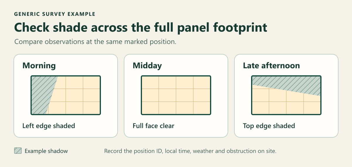
- Log shade on the full panel face. Where practical, revisit the marked position in the morning, around midday and later in the afternoon. Record the position ID, date, local time and weather. Mark the face as clear, partly shaded or fully shaded. For each shadow, note where it falls and which object casts it. Attach a photo or a sketch. If clouds prevent a reliable observation, mark that entry inconclusive.
- Record the gaps. Mark any missed periods and account for changes in sun angle or foliage if the light is needed year-round. A local sun-path estimate can guide a revisit. The U.S. Department of Energy guidance on solar resource and panel angle provides background for that check. Use the observed shade record and a representative charging trial to evaluate the selected position.
Measure the cable route between the connection points
- Agree on the endpoints. Use the model drawing or sample to identify the panel-side and lamp-side points that bound the usable span. The endpoints could be cable exits or connector mating points, depending on the configuration. Mark the same reference points on the site drawing and on the supplier's diagram. Note any length that sits inside a fitting or outside the measured span.
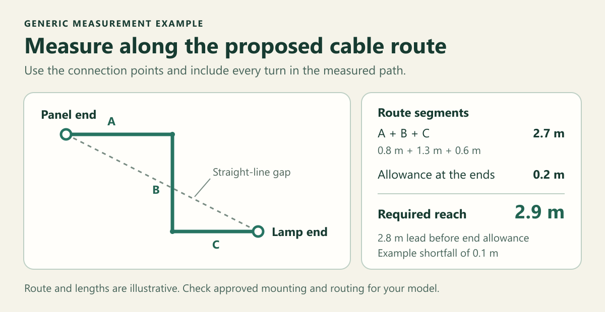
- Follow the proposed route. Use a flexible tape or string between those points, following each turn and change in depth. Record each segment and add them. Mark where the connector needs space to fit or must remain accessible. Record the required end allowance separately so it can be applied once.
- Compare on the same basis. If the supplier states usable length before reserving the end allowance, compare it with the measured route plus that allowance. If the supplier has already deducted the same allowance, compare its figure with the measured route alone. Confirm any approved extension, connector requirements and total-length limit for the exact configuration. If either measurement convention is unclear, leave the reach check pending.
Worked example: Record one site check from survey to sample decision
In this hypothetical record, the lamp position is marked L1, the proposed panel position is P1 and the sample is S1. Keep the same IDs on the elevation, photos and sample sheet. The figures illustrate the recording method and do not describe any LUMELVO model.
| Check | What goes in the record | Result and next step |
|---|---|---|
| Panel face and bracket | P1 on the marked elevation. The sample bracket fits the checked surface, holds the proposed angle and leaves the required access. | Pass for this fit check. Save the marked elevation and bracket reference. Keep the charging assessment separate. |
| Shade observations | 12 May, local time, clear sky. At 09:00, a nearby wall shades the left edge. At 12:15, the face is clear. At 16:10, the eave shades the top edge. Link the three photos to P1. | Observations recorded. Use this log for the trial. Leave other seasons or unobserved periods open if they matter to the operating requirement. |
| Lead reach | The endpoints are marked on both drawings. Segments are 0.8 m, 1.3 m and 0.6 m, totaling 2.7 m. The required allowance totals 0.2 m across both ends. The agreed usable span of the sample lead is 2.8 m before reserving that allowance. | Revise. The required span is 2.9 m, so the sample lead falls short by 0.1 m. Confirm an approved lead option or revise the route. Remeasure and recheck connector fit on the revised setup. |
| Night operation | The final installation route has yet to pass. Record the required lit area, mode and hours on the test sheet before testing. | Pending. Run the night check on the revised setup after representative site charging. Log the charge conditions, start and end times and whether the agreed area stayed lit as required. |
The net-length calculation gives the same result. Subtracting the 0.2 m end allowance from the 2.8 m usable lead leaves 2.6 m for a 2.7 m route. The shortfall is still 0.1 m. Record which basis was used so the next person can reproduce the result.
Record what the sample needs to pass
Test the quoted configuration with its approved connection parts at the proposed position, or document why a substitute position is representative. Agree on the target area, operating mode and required hours beforehand. If the project specifies a measured light level, identify the measurement points and acceptance requirement. Record the sample ID, starting charge if known, daylight and shade, and any supplemental charging used for commissioning.
| Field check | Pass condition |
|---|---|
| Panel position and bracket | The approved bracket fits the proposed surface, holds the intended panel position and angle, and meets the required clearances and access conditions. The shade log corresponds to that panel face. |
| Lead reach and connector fit | The approved lead covers the measured route and required allowance within the documented total-length limit, where applicable. Connectors seat without tension, and the connection points meet the model's protection and access requirements. |
| Night operation | After representative site charging, the sample covers the agreed area for the full required period in the specified mode. For continuous light, log the operating window and any interruptions. For motion mode, check the agreed approaches. Record measured light levels where the project requires them. |
| Parts for the order | The sample ID and configuration match the quotation. The panel, bracket, lead, any approved extension and required connection accessories are each listed as included or separately ordered. |
Mark a check pass when the result meets the agreed requirement, revise when a measured result falls short, and pending when evidence is missing. For each open item, name who will provide the missing information or repeat the check. If the sample was topped up externally, keep solar runtime pending until it passes after representative site charging. Approve the sample for the order after the required checks pass.
Field questions
Can the cable pass through a wall opening?
Only if the model instructions and site requirements allow the proposed detail. Check the connector body size, the required protection at the opening and any access conditions. Have the responsible installer verify the detail before drilling.
What should I verify for an LMV-WL05 inquiry?
Match the quotation to the full configuration on the LMV-WL05 product page. For LMV-WL05-S-24W, ask the supplier to identify the panel and bracket against the 5 V, 35 W panel entry. Send the marked elevation and route sketch with both endpoints, and request the approved mounting positions, usable lead length and any permitted extension for that SKU.
What if the cable reaches but the connector would sit behind fixed trim?
Keep the connection check open. Compare the proposed joint location with the model's access and protection requirements. If the location is unsuitable, have the installer propose an allowed connection point, then remeasure the route to that point and check the available connector clearance.
Can I reuse the survey for a matching entrance on the opposite side of the building?
Use the first survey as a recording template. Give the second panel position its own ID and confirm the orientation, obstructions and measured route there. A mirrored elevation can change both daylight exposure and where the connector ends up.
What if the supplied lead carries a length label but the drawing shows a different usable span?
Record both figures and keep the reach check pending. Ask the supplier which dimension applies between the marked endpoints and whether it includes portions inside the fittings. If a sample is available, verify the agreed span on that sample before comparing it with the site route.
Related products
The Cylindrical Solar Wall Lantern is another wall-light listing. Use the mounting and connection documents for the model actually selected for the site check.
Send your site measurements
Share your proposed layout with LUMELVO. Include the exact configuration, marked panel position, shade log and route sketch with the endpoints, segment lengths and end allowance. Add the required lighting hours and any connector clearance or access constraints.